- #ARDUINO WHILE LOOP BUTTON HOW TO#
- #ARDUINO WHILE LOOP BUTTON SERIAL#
- #ARDUINO WHILE LOOP BUTTON DRIVERS#
- #ARDUINO WHILE LOOP BUTTON DRIVER#
Next, we need to supply 5V to the logic circuitry of the L298N. Because L298N has a voltage drop of about 2V, the motors will receive 10V and spin at a slightly lower RPM. We will therefore connect an external 12V power source to the VS terminal. In our experiment, we are using DC gearbox motors, also called “TT” motors, which are often found in two-wheel-drive robots.

Let’s begin by connecting the motor power supply. Now that we know everything about the module, we can start hooking it up to our Arduino!
#ARDUINO WHILE LOOP BUTTON DRIVER#
Wiring an L298N Motor Driver Module to an Arduino
#ARDUINO WHILE LOOP BUTTON DRIVERS#
This is why the L298N based motor drivers require a big heatsink. This excess voltage drop results in significant power dissipation in the form of heat. The image below shows PWM technique with various duty cycles and average voltages. The shorter the duty cycle, the lower the average voltage applied to the DC motor, resulting in a decrease in motor speed. The higher the duty cycle, the higher the average voltage applied to the DC motor, resulting in an increase in motor speed. This average voltage is proportional to the width of the pulses, which is referred to as the Duty Cycle. PWM is a technique in which the average value of the input voltage is adjusted by sending a series of ON-OFF pulses. A widely used technique to accomplish this is Pulse Width Modulation (PWM). The speed of a DC motor can be controlled by changing its input voltage.

We can only have full control over a DC motor if we can control its speed and spinning direction.
#ARDUINO WHILE LOOP BUTTON HOW TO#
The code below only allows for the program to register the button press when the pin has gone low, then back to high again.If you are planning on assembling your new robot, you will eventually want to learn how to control stepper motors. Let’s add a boolean flag called button_debounce. Preventing your button from triggering the event more than once This would cause your system to be unreliable. Say for example you were using this to trigger a relay, instead of just once you’d be triggering it a bunch of times. When you press the button once, the program will detect this as several button presses and will trigger over and over.
#ARDUINO WHILE LOOP BUTTON SERIAL#
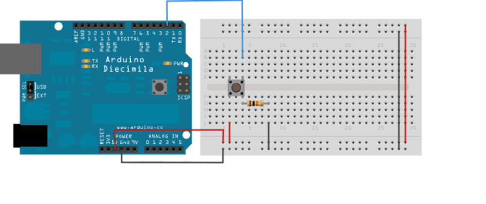
This super simple example will output to your serial monitor every time the button is pressed.īut there’s a problem here. Note that we’ve connected our switch to digital pin 2, there’s a good reason we’ve picked this pin and we’ll go into this later. If you’d like an explanation of what a pull up resistor does and/or what pin floating is, Sparkfun has a great article here.īelow is the basic code for this. Connect your VCC and GND lines and connect your push button along with a 10K pull up resistor to prevent the pin from floating. Start with your Arduino hooked up to your breadboard like in the example below. We’ll then go further in depth to explain the pros and cons of each design. We are going to go through a few iterations of designing a push button circuit for your Arduino project, along with provide different ways of handling this in code.

Stick with me on this because for such a simple concept, this is going to be a long in-depth post. Properly setting up a push button in the Arduino environment isn’t as simple as it first seems. They may seem simple but when you finally hook everything up, you’ll probably run into a few pitfalls. You can use them to trigger all sorts of events and this is great for altering the program state in whatever way you can imagine. Push buttons are great for Arduino projects. Read perfect Arduino button presses every time


 0 kommentar(er)
